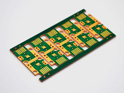
Relax pcb etching tolerance customer required controlling the tolerance of xxx for all traces.
Pcb copper etching tolerance.
If your hole tolerances are zero see below then advanced circuits will assume that you are ok with our default hole tolerance.
Where possible design to printed circuit board manufacturing industry standard mid range tolerances.
The production of printed circuit boards is carried out according to the valid ipc guidelines and standards et al.
The minimum trace width space is 0 003.
If you use these tolerances you should be able to source your boards from any manufacturer in the world without cost penalty.
Pcb is an acronym that stands for printed circuit board that helps to connect active passive electronic components with pads tracks and lines incorporated on a laminated copper sheet.
Our default hole tolerance is listed above.
0 003 custom spec upon request 1 oz and 2 oz finished copper weight and 3 oz finished copper weight when starting with 2 oz foil only.
Ipc a 600 class 2 and on the basis of following technical specifications.
Normally tolerance will occur due to pcb processing steps such as electroless copper solder mask and other types of finish on the surface.
Board thickness tolerance t 1 0mm 0 1mm.
The ipc 4562 and ipc a 600 define both the acceptable thickness and tolerances for both the base and.
A number of stages are involved in proper pcb fabrications which include designing layout routing etching troubleshooting.
Start copper or base copper the copper thickness as received from our suppliers.
For a board of this thickness it is not unusual to have a thickness tolerance of 0 15mm.
Place the pcb into the etching solution and agitate for 25 30 minutes or until all the copper has dissolved around the design if you would prefer not to agitate by hand here is another instructable i created on how to make a agitator using an old cd rom drive.
Board thickness tolerance t 1 0mm 10.
When we consider the layer copper thickness on a pcb we refer to.
Trace width is the minimum width of a copper feature usually traces.
End copper or finished copper this is the final thickness of copper on the finished pcb.
Copper spacing is the minimum air gap between any two adjacent copper features.
Note when calculating thickness that the supplier of the materials for inner layer cores quotes thickness values that do not include the copper weights.
The standard thickness of a pcb is normally around 1 6mm.
However our standard tolerance for line width is 20 or 1 mil tighter tolerance can be achieved with special processing.
Differing requirements of the customer must be explicitly agreed.
Hdi or mft boards can be produced with smaller tolerances.

